Multi-Carriers LTE RelayDAS
The majority of cellular phone calls take place inside, but cell networks are outside. 80% of business users inside complain of poor coverage or dropped calls. A building’s materials, while improving energy efficiency, will block or inhibit cellular service from the outside network. Building owners need a high-quality solution that can serve the middleprise and not take a year to deploy. Addressing cellular infrastructure for small to mid-size enterprise (middleprise – from 15,000 square feet to 500,000 square feet) has hit a major challenge in terms of who pays for the in-building system. Operators may be willing to subsidize enterprise solutions for large-scale customers that are larger than 500,000 square feet (usually in the form of a classic DAS), but the ROI for a middleprise customer installation is just not sufficient to justify the carrier’s cost, or to inspire the carrier to fast resolution.
HELIOS® LTE Multi-Carriers RelayDAS™ is an Active DAS Hybrid based on HELIOS® patented L2 Relay solution that solves the problem of poor cellular coverage in middleprise buildings. Compared to traditional Repeater, which typically lower network capacity due to repeater cannot distinguish desired signals from interference and noise, the L2 Relay enables SINR improvement, coverage extension and capacity enhancement by adaptive signal equalization, baseband decoding, encoding and signal regeneration. The PLMN is programmed to ensure the L2 Relay will only work on the specified PLMN and automatic lock the service cell. With built-in baseband modem, the L2 Relay will be able to scan all cells of telecom operator and decode MIB & SIB to obtain PLMN ID, MCC, MNC, PCI, Band, SNIR, RSRQ, RSRP/RSCP, Downlink BW, Uplink BW, Downlink Frequency, Uplink Frequency of Services Cell and all Neighbor Cells lists, even can accurate reverse link power control delivery to eNB from L2 Relay by learning the PRACH power that eNB expect to receive based on the signaling message from eNB without degrade macro network.
HELIOS® LTE Multi-Carriers RelayDAS™ can support max four LTE carriers (operators) in three frequencies bands simultaneously, utilizing up to superb 115dB system gain with maximum 60dB dynamic automatic power level compensate algorithms delivers a stronger signal and provides a larger coverage footprint in environments where the incoming signal is weak. This ensures the strongest possible signal is sent to the inside antennas and self-configuring and self-optimizing whatever various types of coaxial cable used on site, even using low cost 75ohm CATV RG-6 coaxial cable. And embedded Power-Over-Cable (PoC) features enables HELIOS® LTE Multi-Carriers RelayDAS™ can be installed in just days, and at a price point that meets the middleprise budget.
HELIOS® LTE Multi-Carriers RelayDAS™ mainly consists of two parts as below:
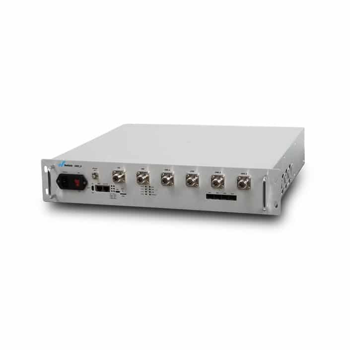
- Network Unit (NU): The Network Unit is the master unit of the total HELIOS® LTE Multi-Carriers RelayDAS™ system. The NU accepts Donor signals from the outside cellular network by Donor Antenna, and Signal source from the donor antenna is connected to the NU. Then it will be processed as adaptive signal-equalization, baseband-decoding, encoding and signal-regeneration and passes that service over coaxial cabling to CUs mounted where cellular service is needed. The NU scan all cells of telecom operator and decode MIB & SIB to obtain PLMN ID, MCC, MNC, PCI, Band, SNIR, RSRQ, RSRP/RSCP, Downlink BW, Uplink BW, Downlink Frequency, Uplink Frequency of Services Cell and all Neighbor Cells lists, it will only work on the specified PLMN and automatic lock the service cell, even can accurate reverse link power control delivery to eNB from NU by learning the PRACH power that eNB expect to receive based on the signaling message from eNB to ensure no degrade macro network. Embedded WEP management GUI centrally monitor, configure and manage the whole system.
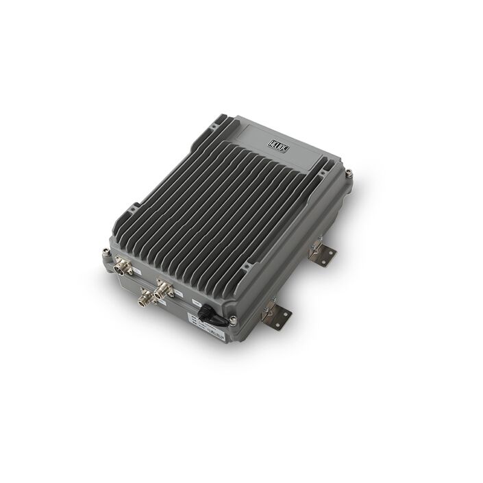
- Coverage Units (CUs): it is the remote unit of the system that rebroadcasts the donor signals and will be directly connected to the coaxial cable, the CUs contain their own transmit amplifiers and are powered from the NU using Power over Cable (PoC). This allows for flexible placement of the CU’s since AC power at the site of each CU is not required. With four (4) Coverage Units, a combined in-building coverage range of up to 50,000 sq.ft. per system can be achieved, or expandable to eight CUs via Non-DC blocked power dividers. Up to 20dBm output power per band sent to antennas to provide a larger coverage footprint in environments.
FEATURE
- Embedded HELIOS own 4G Baseband Processor (Model: HE1885)
- Auto select frequency and bandwidth basis on UARFCN & PLMN code
- Service Cell locked feature to mitigation intercell interference especially on the edge of cells
- Support max four LTE carriers (operators) in three frequencies bands
- Enhancing capacity due to the enhanced MCS and improved service time allocation by better SINR
- Advanced adaptive signal equalization, baseband decoding & encoding and signal regeneration enable better noise immunity
- Unique high-speed RS-AGC function stabilizes coverage area and prevent fluctuating output power from Relay to eliminate Respiratory-Effect
- Accurate reverse link power control by learning the PRACH power that eNB expect to receive based on the signaling message from eNB without degrade macro network
- Embedded Signal QoS Analyzer (Before/After Relay)
- Wireless backhaul for more fast, flexible and accurate deployment to improve throughput on blind and cell edge
- Peaceful coexistence with current LTE macro without any change & update on core network
- Embedded hardware accelerators design for low latency to prevent communication quality degrading
- 2*RJ-45 Port for Local Control and Alarming on an IP Web Browser GUI
- SNMP V2 & V3 support with a MIB File
- Supports Remote Control via Wireless Cellular Modem
- Innovative Power-over-Cable (PoC) feature enables flexible & simplifies installation
- Each NU supports up to four-ways RF output to four CUs, or expandable to eight CUs via Non-DC blocked power dividers
- Utilizing up to superb 115dB system gain with up to 60dB dynamic automatic power level compensate algorithms delivers a stronger signal and provides a larger coverage footprint in environments where the incoming signal is weak. This ensures the strongest possible signal is sent to the inside antennas and self-configuring and self-optimizing whatever various types of coaxial cable used on site, even using low cost 75ohm CATV RG-6 coaxial cable
SPECIFICATIONS
Network Unit
Electrical Specification
Frequency Range (Customized): LTE FDD Band 1, 3, 7 and 8
Band Selectable: Up to three Bands
Total Sub-band or Operator number: Up to 4 carriers(Automatic select based upon the operator)
Gain: 65dB±2dB per port
Gain Adjustment Range: 30 dB in 1 dB Step
System Passband Ripple (typ.): ≤+/-2.5dB
Uplink RF Output Power: 23 dBm per band
VSWR: <1.8
Number of Remote Unit support: 8
Alarm Detection: Input over power, High temperature, Unlock, RU fault and etc.
Local Alarm Indications: 1. LED alarm display 2. Laptop via local RJ-45 port (IP Web Browser GUI)
I/O Impedance: 50 Ohm
MTBF: 100,000 Hours
Power Supply: 100~265V AC, 50~60Hz
Power Consumption: ≤100W exclude RU POC supply
SNMP: SNMP V3+Mib File
External and Antenna Connection
Connector: RF: N-Female/Monitoring: RJ-45
Monitoring: Web browser GUI via RJ-45 Port/Additional RJ-45 Port for external Ethernet or Wireless Modem
Mechanical Specification
IP Rating/Cooling: IP53 Convection
Temperature Range: -20℃ to +55℃
Relative Humidity: Max 95%
Dimension: 375mm*226mm*80mm
Weight: 7KG
Coverage Unit
Electrical Specification
Frequency Range (Customized): LTE FDD Band 1, 3, 7 and 8
Band Selectable: Up to three Bands
Downlink Output Power: 20 dBm per band
Gain: 50dB ± 3dB
Gain Adjustment Range: 30 dB in 1 dB Step
System Passband Ripple (typ.): ≤+/-2.5dB
VSWR: <2
Alarm Detection: Current error, output under power, communication error alarm
I/O Impedance: 50 Ohm
MTBF: 100,000 Hours
Power Supply: 48V DC POC from MU
Power Consumption: Max. 30W
External and Antenna Connection
RF Connector: RF: N-Female
Mechanical Specification
Temperature Range: -20℃ to +55℃
Relative Humidity: Max 95%
Dimension: 195mm*130mm*47mm
Weight: 1.5kg